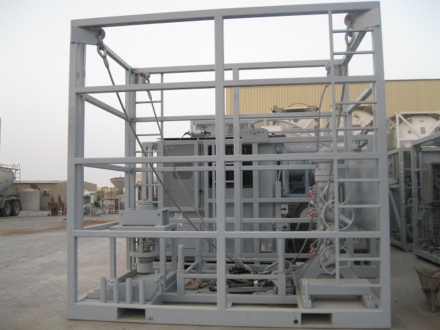


DESCRIPTION
skid mounted ctu consisting of control cabin, power pack, tubing reel, power hose reel, tot bop and stripper, and injector/bop transport skid.
1.0 control cabin model 301 (zone ll) – skid dimensions 168” l x 94” w x 98” t - 13,000 lbs skid mounted with crash frame.adjustable two point lift, with sling. sling to have vendor product certificates.
1.1 telescoping control cabin to be 90" long by 80" wide constructed of composite materials.
1.2 two (2) side access doors (one each side), sliding type window, rain gutter and stainless steel hardware. tinted front window with removable, hinged, metal guard, rain gutter and windshield wiper. large sliding type windows on side walls. flooring to anti-slip.
1.2.1 two (2) exterior floodlights to be installed on upper front of cabin and two (2) interior fluorescent lights installed at rear of cabin and two (2) exterior floor lights mounted above porch. all lighting to be explosion proof-wired to zone ll standards per nfpa 70 (nec). electrical to be 60 hz.
1.2.2 captain's chair with armrest provided for operator comfort, one (1) padded bench seat, 20" wide, against left side wall.
1.2.3 one (1) three pen chart recorder provided.
1.2.4 cabin inside height is 76".
1.2.5 explosion proof-zone ll; roof mounted, 220vac air conditioner/heater.
1.2.6 150’ powercord with zone ll plug and mating receptacle.
1.3 integral hose and bop storage area located in front of cabin includes a removable bulkhead panel for hose connection. all hoses equipped with aeroquip quick disconnects on one (1) end, tagged with stainless steel washers, and stored on posts. hose lengths are as follows:
1.3.1 bop hoses are 125'. last 50’ to be fireproof hose.
1.3.2 injector hoses are 125'.
1.3.3 tubing reel hoses are 50'. 480k coiled tubing unit specification no.: 201a – 8638a page 2 of 6
1.3.4 power unit hoses are 30'.
1.4 "l" shape design control console with shelf. control console contains the following:
1.4.1 6 bank bop control valve with individual spring loaded
locking handles. one of the six banks will operate the shear seal bop. bop to have emergency backup circuit supplied from an auxilieary air-over-pump.
1.4.2 bop pressure gauge.
1.4.3 air regulator valve, snaptite valve, and gauges to operate
two dual acting stripper circuits. hydraulic supply for stripper is air-over-pump with manual override.
1.4.4 hydraulic weight indicator for customer supplied hr-480 injector, 0 - 100,000 lbs. pipe heavy and 0-50,000 lbs. (pipe light) with dual english / metric scales mounted center of panel.
1.4.5 pressure regulator valve with isolation and gauges for three (3) injection traction circuits.
1.4.6 control valve for injector speed and direction, with 0-1000 psi gauge.
1.4.7 valve for injector two speed and brake control.
1.4.8 pressure control valve for setting remote injector pressure control.
1.4.9 valves for injector chain and reel tubing oiler.
1.4.10 hydraulic pressure gauge for injector pull and push.
1.4.11 hydraulic valve, 3-bank for reel control. i.e. reel pay-off or
take-up, levelwind raise and lower and levelwind override.
1.4.12 relief valve for reel tension control.
1.4.13 pressure gauge for reel tension.
1.4.14 valve for reel brake with gauge.
1.4.15 two (2) 6", 4:1 10,000 psi pressure gauges for wellhead pressure and circulating pressure to be mounted to right of weight indicator.
1.4.16 air control for engine speed, kill and emergency kill.
1.4.17 pressure control with gauge for injector outside chain 480k coiled tubing unit specification no.: 201a – 8638a page 3 of 6
tension control.
1.4.18 full instruments including tachometer.
1.4.19 zone ll ctes data acquisition system installed. orion lv software license with associated cables, transducers, bulkheads and cerberus modeling and fatigue tracking software. laptop computer included.
2.0 power unit – high pressure open loop design (zone ll)
dims- 90" wide x 102" long x 96" tall- 15,000 lbs
2.1 skid mounted with crash frame, forklift tubes and 4-point lift with slings. slings to have vendor product certificates.
2.2 model 8v-92n remanufactured detroit diesel engine, with a pyroban (group ll category 3g t3 a), certified for atex zone ll service. engine to have spark arresting muffler. radiator sized for 50 48°c ambient. engine has system shutdowns for over temperature, overspeed, loss of oil pressure, loss of coolant, and high exhaust temperature as required for zone ll operation. engine will also have spark arrestor exhaust, sealed crankcase, crankcase breather flame traps, remote shutoff device, fuel shutdown valve, and anti-static fan drive belts and blades. engine is for export with no epa regulations rated at 364 bhp @ 2100 rpm.
2.3 air starter system. 2.4 air compressor is 12 cfm. 2.5 air operated engine speed, kill and emergency kill (air to run). 2.6 piston type high pressure open loop pump for injector drive. 2.7 vane type double pump for reel, bop, and auxiliary functions. 2.8 pressure compensated, 4-way vale for injector control. 2.9 selector vale for switching hydraulic power to auxiliary functions. 2.10 air-to-oil heat exchanger, sized for 48°c ambient. 2.11 three (3) 10 – gallon bladder type bop accumulators for bop. 2.12 fuel tank capacity 100 gallons, with diverter valve for external fuel supply. 2.13 hydraulic oil reservoir capacity 240 gallons. 480k coiled tubing unit specification no.: 201a – 8638a page 4 of 6 2.14 air reservoir capacity 30 gallons. 2.15 ladder integrated into protective frame. 3.0 model 3020 tubing reel: direct drive – 177” l x 98” w x 151” h – capacity of 15,000’ of 2.00” tubing - gross lift capacity is 85,000 lbs.
3.1 skid: full-length drip pan; drain tubes in each corner; reel pivot provisions; 6” x 14” forklift pockets at 84” centers; “d-rings” on each corner for skid tie downs.
3.2 reel: double recessed drum design with continuous concave core to shaft structure; 84” diameter core x 70” between flanges x 148” diameter outer flanges; two lift lugs at shaft; flanges have expanded metal panels; guide arch for tubing entering the core. with tubing.
3.3 drive: planetary direct drive with integral brake capable of spooling 2” tubing in at 2,500 psi hydraulic pressure or less; crossover relief valve protection for motor.
3.4 levelwind: mechanicaly driven diamond leadscrew with adjustable clutch system; remotely operated hydraulic motor to override in either direction; dual-bar crosstrack design; hydraulicly raised to working position; couterbalance valve to maintain elevation.
3.5 relief valves: motor case drain and brake protected by pop-off relief valves.
3.6 chain guards: all chains have removable protection guards; levelwind chain guard has hinged cover for quick change out of sprockets and clutch adjustment.
3.7 pipe plugs: expandable neoprene plugs fully recessed in skid secured with 1/8” plastic coated lanyards. 3.8 name plate: stainless steel identification plate attached.
3.9 non-lift frame: removable protection frame; two ladders at opposite sides provide access to top of frame; pins attach frame to skid.
3.10 counter kit: hydra rig model rc-203 tubing, variable size, counter with vertical slide mount to compensate for tubing pay-off angle; dressed for 2.00" tubing, measuring in feet.
3.11 internal plumbing fmc 2x2 valves standard: non-h2s fmc integral 1502 type fittings rated at 10,000 psi; tee for ball launching or 480k coiled tubing unit specification no.: 201a – 8638a page 5 of 6
wireline adaptation; 2x2 shutoff valve between swivel and drum core. plumbing to have vendor product certificates.
3.12 external plumbing fmc 2x2 valves standard: non-h2s fmc integral 1502 fittings rated at 10,000 psi; dual inlet connections and 2x2 shutoff valves between swivel and inlets; integral mounted 4:1 debooster to monitor circulating pressure. plumbing to have vendor product certificates.
3.13 bulkhead connections: male aeroquip quick disconnect fittings; plastic caps. 3.14 lubrication system: tubing oiler mounted from counter; 30-gallon lubrication reservior; fill cap; level gauge; 140 psi relief valve; air actuated amot valve; air regulator; air pressure drain valve; lube drain valve.
3.15 hoses: hydraulic and grease lines are standard climate rated. 3.16 two point lift system: spreader bar arrangement for lifting entire loaded reel assembly or loaded drum only; solid link design; spreader bar stores against rear frame members when not in use. sling for reel assembly with vendor product certificates.
3.17 data acquisition: mount for encoder installed. 3.18 tie-downs: reel drum locked into transport position by a chain and binder system on one reel flange. 3.19 circulating swivel: hydra rig 10,000 psi 1-1/2” bore swivel; proof- tested to 15,000 psi; suitable for non-h2s service; flange mounted with compression face seal; protected by removable steel plate; components exposed to circulating fluids are replaceable. swivel to have hydra rig data package.
4.0 injector head hydra rig model hr-480 5.0 texas oil tools pressure control equipment
5.1 texas oil tools solid block blowout preventer: 4.06” quad, 10m with 4:1 hydraulic debooster. pressure test sub for bop stand and test/lift bail to test bop’s on stand.
5.2 texas oil tools, 4.06” 10m side door stripper. 480k coiled tubing unit specification no.: 201a – 8638a page 6 of 6
6.0 injector power hose reel/hoses
6.1 skid mounted, hydraulically powered hose reel to accommodate two (2) 1-1/2" x 125' long injector power hoses with hydraulic inc. connections. 6.2 one (1) 25’ jumper hose bundle for connection of power hose reel to power unit. hose bundle to store in transport skid.
7.0 injector head and bop transport skid
7.1 the injector transport skid has drip pans incorporated into the skid base with drain plugs. 7.2 the skid has a crash-frame with a 4-point lift with slings. slings to have vendor product certificates. 7.3 the transport skid is for transporting the injector, gooseneck, bop and stripper. the gooseneck pivots vertically for placing in skid. 7.4 a stand is provided for a 4.06” 10m quad that is capable of being used to pressure test the bop's to 10,000 psi wp. that has a 3/8" npt port near the base plate and has a needle valve. the stand will be of adequate size for the bop's to be stable on it when set down on uneven ground. 7.5. skid designed to transport injector, bop, gooseneck, legs, and stripper.
8.0 general specifications
8.1 complete unit sandblasted, primed and painted to hydra rig specification to customer specified color. the entire unit will be painted gray ral7040 (jones blair ahw 6010). 8.2 complete unit assembled and tested, with the customer's witnessing acceptance, at hydra rig's fort worth, texas, usa facility.
8.3 three (3) owner's manuals and cd's will be supplied with each unit. coo and coc to be issued for unit.